updated: 07/11/2022
Since the release of the MMDVM in early 2016, Johnathan Naylor’s (G4KLX) creation has hit the ground running throughout the ham community. This simple creation has put the power back into the hands of radio operators around the world allowing them to build and tinker with digital voice systems, breaking down the barrier of needing expensive commercial hardware. The MMDVM is a hardware and software component that can interface radios to a computer, like a raspberry pi, turning normal analog radios into digital radios, much like a TNC for packet radio. The MMDVM-Repeater board is a lot like a hotspot, except it doesn’t have a radio built onboard. Instead, it uses cables to wire directly into the IO pins of the radio(s) you choose. The MMDVM/Raspberry-Pi combo will turn a single analog radio into a high powered hotspot or 2 radios into a fully featured digital voice repeater. The MMDVM_Host software counterpart is opensource and feature rich giving users access to the following digital modes:
- D-star
- DMR
- Yaesu System Fusion
- P25 Phase I
- NXDN 4800
- POCSAG
After following this article you will be able to put together a multimode amateur digital repeater or high powered hotspot that can be connected to the internet for world wide digital communication. Through proper coordination, given digital’s IP connectivity and features, Ham radio operators around the world can build fully connected systems, allowing remote parts to have access to RF communication. A connected digital environment allows us to leverage MESH networks like Broadband Ham Net or ARDEDN in events where the internet may not be reliable. Think about it, the ham community can build a large network that has the ability to be “offline” and still allow for clear digital voice communication. How cool would that be! If its easy and cheap to build and can be done in areas with no internet, that’s helping humanity. Baby steps though, lets just get this digital node built.
7 Items needed:
- Rasperry Pi 3 = Amazon
- Micro SD card = Amazon
- MMDVM board = STM32-DVM OR Zum MMDVM (Discontinued) OR Micro-Node TEENSY
- NOTE: These are NOT hotspot boards, they are different and built to interface with a physical radio.
- 1 or 2 radios with a 9600buad port, or a discriminator tap.
- A simplex node will use 1 radio
- A duplexed node will use 2 radios and will require a duplexer.
- Choose a radio carefully keeping in mind duty cycle and heat dissipation, EXTREMELY IMPORTANT. A cooling fan will be an absolute must! Motorola radios are great, but have drawbacks if you don’t have access to programming software. The old Icom/kenwood sitting in the corner collecting dust is a viable option. Many people are using the Yaesu DR-1X repeater for duplexed operations (must not be firmware updated, i.e. FR model, or the DR2).
- A cable to connect from your radio(s) to the MMDVM*
- This can be a difficult part for those who don’t know how or don’t like to solder. There is no single article or how-to page for making the cable. This is where your inner geek, and solder hands can come to play.
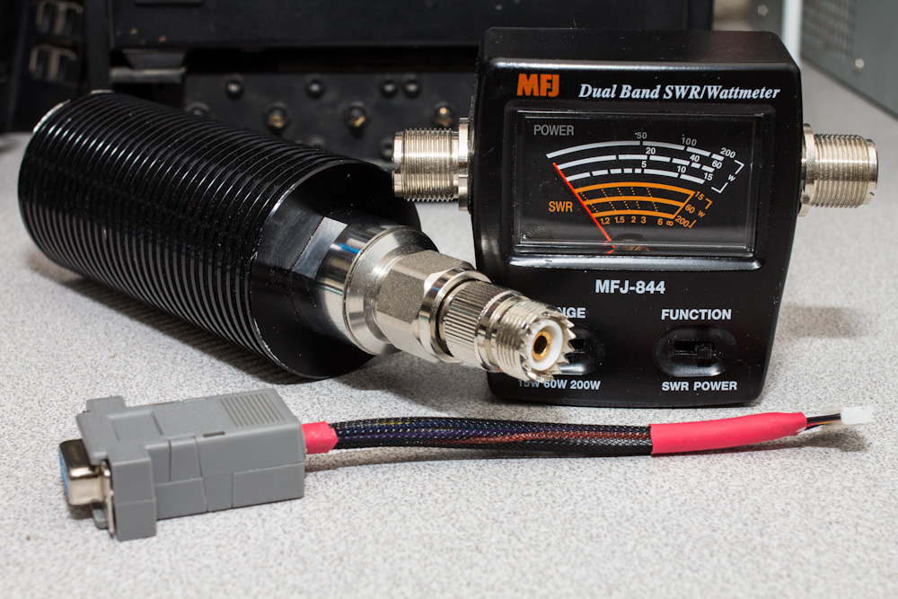
- Other items include, a dummy load and SWR/Wattmeter for testing, power supply, and an antenna when you are ready for the air. Please help keep the finite airwaves clear of testing and un-needed traffic. Please use a dummy load during all your initial tests and any future tweaks you may need to do.
- The Pi-Star Image for the SD card
These 7 items will give you:
- Ability of up to 5 different digital modes, P25, DMR, D-Star, Yaesu Fusion, NXDN, along with some cross-mode capabilities with on the fly PTT access. Meaning, just key up your radio and it handles the rest.
- A web interface that can be accessed from a smart phone or computer to control the node remotely with real-time activity.
- A “high-powered” hotspot or repeater. Anything deployed, no matter the coverage, helps add to the infrastructure. Just be sure to advertise the repeater/node. Sharing is caring!
The layout will look something similar to this, excluding the Arduino (courtesy of f5uii.net)
Building the MMDVM node:
-
- Burn the image to the SD: Download and burn the Pi-star image to the SD card. On windows I use Etcher. Its the simplest and easiest burning tool I have found to date. If you don’t have windows, or have never burned an image to an SD card before, there are many tutorials online
- Plug the MMDVM into the PI: Depending on which MMDVM you go with, either plug it into the GPIO pins of the Raspberry PI or the USB port.
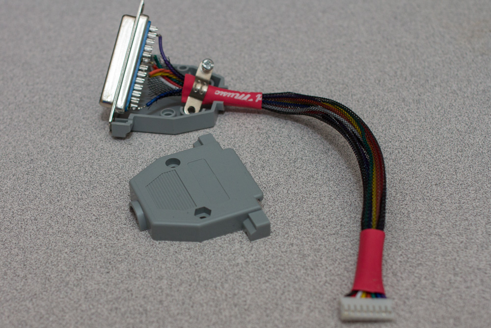
- Make the interface cable: For those who do not like to solder, this step could be difficult….
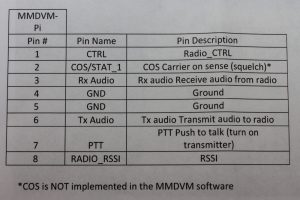

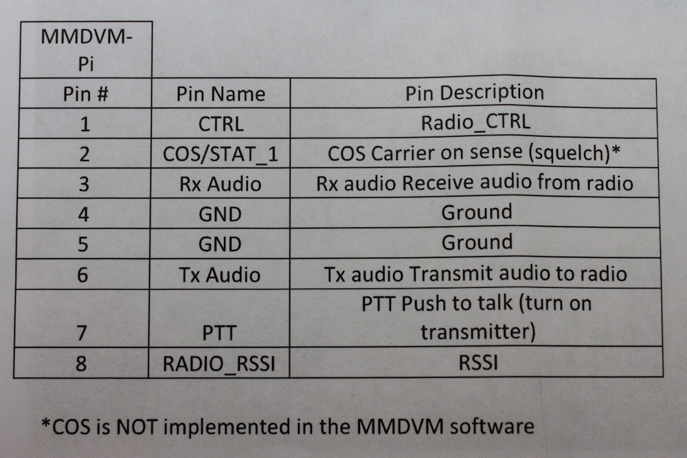
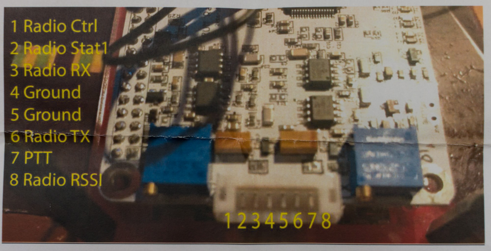
- You will need to look in the manual of your radio for its pinout. The tables below are for connecting Motorola CDM Radios or the DR1 to the ZUM Radio MMDVM
Moto CDM - MMDVM pinout
MOTO TX --PIN 3 PTT MMDVM -- PIN 7 BLUE PTT MOTO TX -- PIN 5 FLAT AUDIO IN MMDVM -- PIN 6 GREEN TX AUDIO MOTO TX -- PIN 7 GROUND MMDVM -- PIN 4&5 ORANGE/YELLOW GROUND MOTO RX -- PIN 11 FLAT AUDIO OUT MMDVM -- PIN 3
WHITE RX AUDIOMOTO RX -- PIN 8 COR/COS MMDVM -- PIN 2 RED COS MOTO RX -- PIN 7
GROUNDMMDVM -- PIN 4&5 ORANGE/YELLOW GROUND Yaesu DR1 - MMDVM Pinout
DR1 -- PIN 2 PTT MMDVM -- PIN 7 BLUE PTT DR1 -- PIN 7 AUDIO RX MMDVM -- PIN 6 GREEN TX AUDIO DR1 -- PIN 5 Ground MMDVM -- PIN 4&5 ORANGE/YELLOW GROUND DR1 -- PIN 8 Disc. out MMDVM -- PIN 3
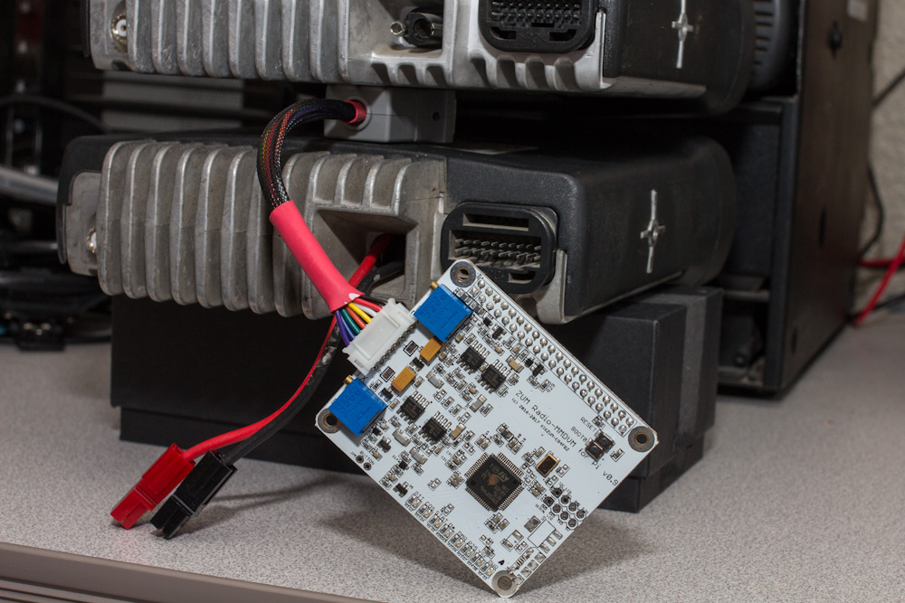
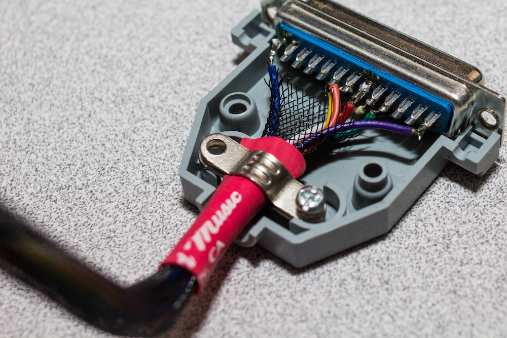
WHITE RX AUDIODR1 -- Pin 4 COS MMDVM -- PIN 2 COS DR1 -- Pin 5 DR1 -- Pin1 (Yes you are reading that right, jumper these pins together on the DR1) This enables "repeater mode" DR1 -- Pin 10 DR1 -- Pin 11 (Yes you are reading that right, jumper these pins together on the DR1) This enables the 15din remote port. - You will end up with something like this….
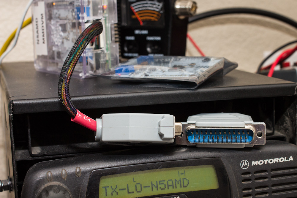
- The DB25 connector was used in this case because I can unplug the MMDVM and plug in the DMK URIx for analog all-star. You can choose to wire directly without a connector or use a DB9 for example. The choice is yours.
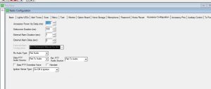
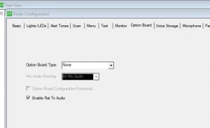
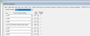
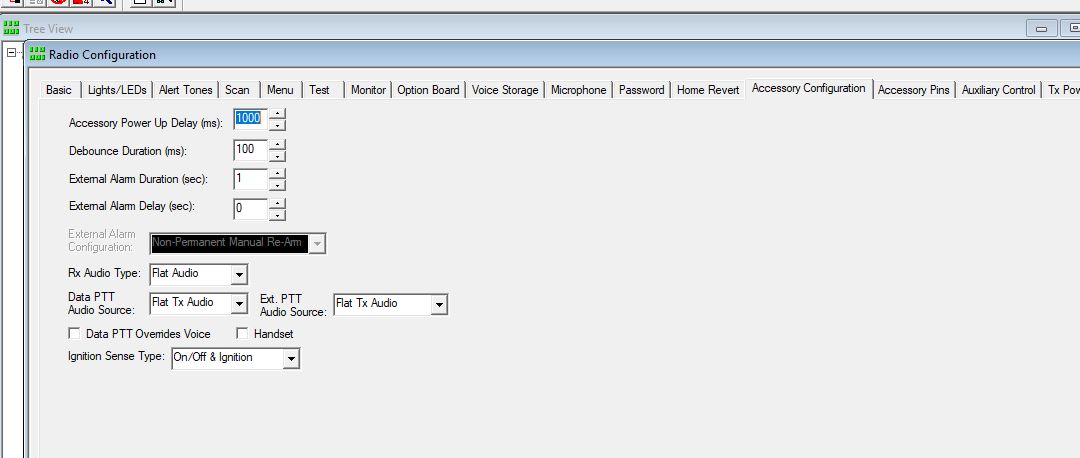
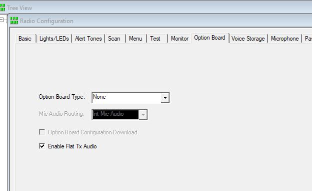
- Program the radio: Pick a frequency and program your radio(s). Not sure what frequency to use? Here is the Texas Band plan for example. Just make sure you don’t over step any local repeaters, national calling frequencies, or Satellite Frequencies. In other words, please use common sense. As part of programming your radio, if you are using CDM/commercial radios, make sure all your settings are set to FLAT AUDIO.
- Boot the PI up: Now that you have the cable made, radios programmed, and the Pi-star image burned to the SD card, put the SD card in the PI and boot it up with a network cable plugged into your local network. *Leave the radio(s) unplugged from the MMDVM for now.* We dont want to accidentally key the radio with no antenna or burn anything up with bad SWR etc…
- Navigate to the dashboard: If your PI is booted and has network connectivity all you need to do is open a web browser on a computer or your phone and go to…
- http://pi-star/admin/
- Default credentials– Username: pi-star Password: raspberry
- Setup Pi-star: This video by W1MSG is an excellent video that goes over the initial setup of pi-star.
- Basically the video walks through filling out the required fields, enabling modes you want and configuring those modes. Pi-Star is an amazing, super easy, straight forward tool. Even if you have never used it before, once you are logged in, its easy to get around the interface.
- Key up and test it: Once pi-star is configured, go to the dashboard and plug your radio(s) into the MMDVM, making sure you have a dummy load or an antenna plugged in. Key up on the frequency you chose on the digital mode you chose. You should see on the dashboard in Green “RF” and the red PTT light on your MMDVM light up.
- One snag I ran into was by default TXINVERT was set to on or ‘1’. I was hearing digital noise, but nothing was decoding it. I fixed it by going into expert mode in pi-star (pi-star.local/admin/expert) and setting it to off or ‘0’ under MMDVMHost. TXINVERT and RXINVERT depends on the radio you use. This may require trial and error.
- Adjust the pots: If everything seems to work at this point, the next step is to tune the mmdvm’s adjustable audio pots. This is a very tedious process and requires A LOT OF PATIENCE. Most of the time, the pots are already set from the factory and usually don’t need adjusting. But if you are seeing constantly high BER or not getting audio back, you will need to adjust the pots. There are 3 ways you can tune the pots to achieve desirable BER/Audio. DMR is the most picky and requires even more patience.
- Tuning the duplexer: If you have taken the leap to build your first repeater, let me personally say congrats and thank you. Building your own repeater is no easy feat, but is very very rewarding. I am more of a computer person than an RF person, so tuning my own duplexer took quite a bit of help from friends and lot of research online. I found the cheapest way to get a duplexer “professionally” tuned while still doing it your self, is with a USB Vector Network Analyzer or VNWA. Its still very expensive, but comparatively speaking to its commercial counter part, it performs very well. This is the one I used, since I had access to one:
-
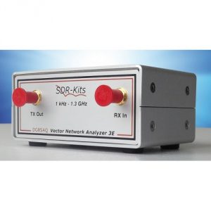
courtesy of sdr-kits.net - This is the SDR-Kits’ DG8SAQ USB-Controlled VNWA. They run for about $400. If you are looking for a tool for the shack, you will invariably find use for one. I personally think USB VNWAs are worth the investment.
-

- Open firewall ports : Opening ports may be optional depending on your network. Most of the time uPnP if implemented on your network properly is “good enough”. However, if you notice other devices cant link inbound or features like callsign routing are not working, you many need to open ports.
- UDP 62031 — Homebrew repeater protocol
- UDP/TCP 20001-20009 — DPLUS
- UDP 30001 — D-EXTRA
- UDP 30051,30062 — DCS client
- UDP 40000 — D-Star call routing
- TCP 9007 — IRCDDB
- UDP 20011-20014 — Dstar repeater
- For more information: Brandmeister page & Dstar101
I have my Repeater Built, Now What?
- Advertise it, so others can use it too. Repeaterbook is a great start!
- Advertise your new D-Star Repeater
- If your new repeater is on DMR, make sure you get a repeater ID from radioid.net
- Make your own reflector
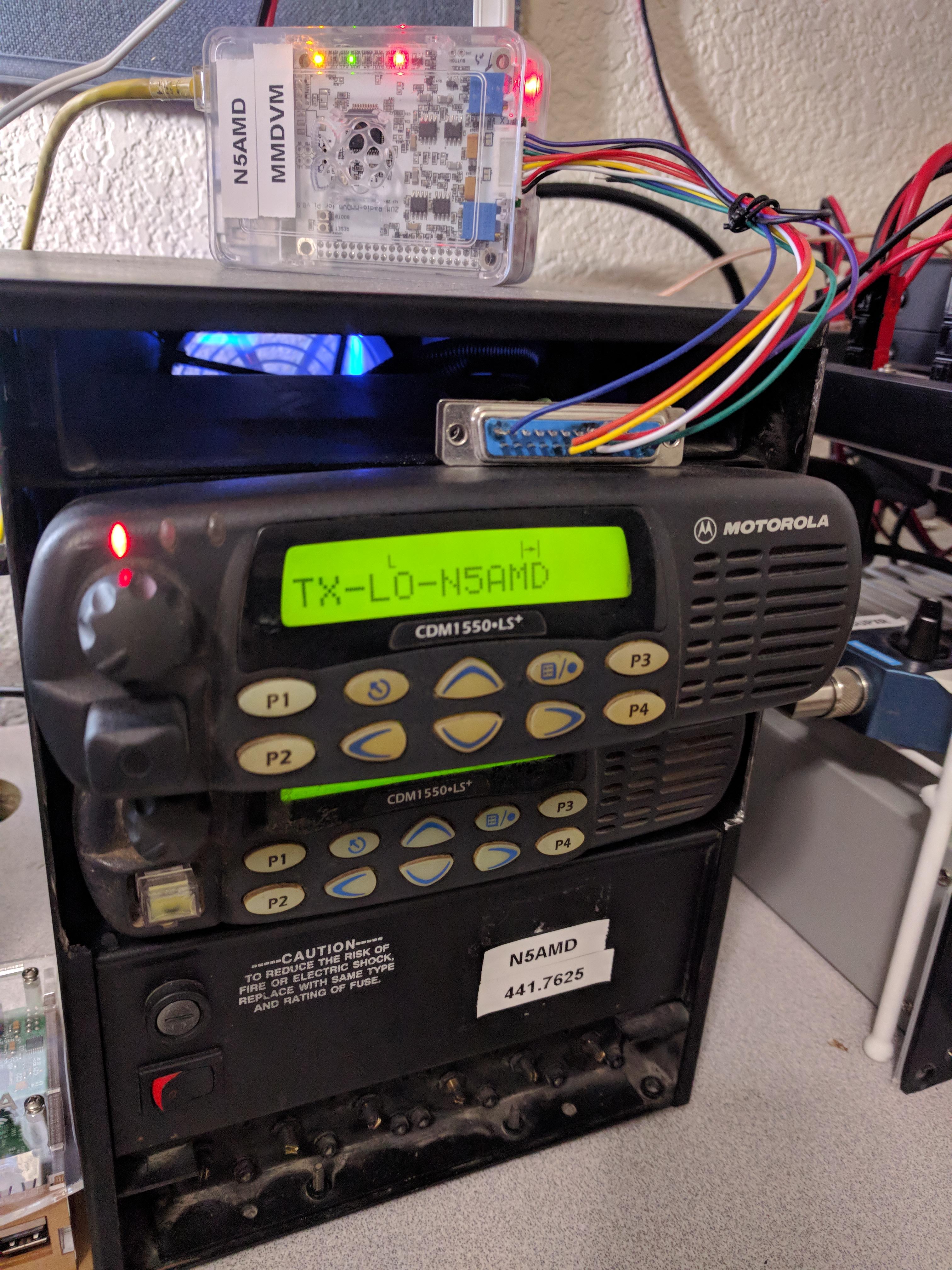
Here is the N5AMD Repeater. The radios were in a trash pile destine to be destroyed. In a digital world, analog radios are being thrown to the side for many commercial 2-way companies. They have been revived and now serve the community helping hams learn about the world of digital radio. From top to bottom…
- MMDVM/ Raspberry Pi 3
- Motorola CDM1550LS+ 2x
- 15amp Power supply
- Celwave UHF Mobile duplexer
- Motorola GR300 case slightly modified to fit the CDM1550s